If I had time to re-render my scene I would like to change the material that was applied to the window inside the room. When you look at the animation it looks like a skyscraper is sliding past the building as you're moving in the room.
This is because i originally applied a map to the envirnoment of the scene and made the window see through. The problem i had with that is that the image didnt look straight when looking out the window. After this I added a new material to the window, which had the skyscraper scene as a diffuse map and this gave a better look, at the time i forgot to remove the environment map and therefore i get this error when running the animation.
Friday, 12 December 2008
A few problems
When animating the scene i found a few problems along the way.
I started off with the camera at the beginning of the corridor and moved this down whilst looking at some of the posters on the wall. I done this by simply turning the auto key feature on and then moving the camera down whilst moving the frame slider down.
The first problem that i had encountered was that it was very difficult to get the hand to open the door the way i wanted it to.
When first moving the hand into the scene, as the hand approached the door handle i adjusted the fingers to make it see as though the hand was getting ready to grip. When i did this initially the hand became very distorted and looked a bit of a mess. To resolve this i adjusted each finger at a time, all of which seem to be ok. I then adjusted the thumb which seemed to be causing the probelem. When this was moving into the door handle the thumb position just needed to be moved up slightly, giving a more smooth feel.
I also then found that it was very hard to get the door handle and the hand to move together. I tried creating a link between the 2 objects but when i played the animation it messed up the position of either the hand or the door handle. The only solution to this i could find was to turn the auto keyframe on and adjust the position of each object every 3 frames to give a smooth looking animation.
When creating the turning page as i had 2 pages each with a different material applied, which were stuck together i found it very hard to animate this turning, without one over lapping the other. This was also a very long process, in which i had to note down how much twist and bend i applied to one and then apply the same to the other. In the end i got the result i wanted.
Need a Hand!
When thinking about starting the animation, i decided that I would like to create a hand so that it can be seen opening the door when entering the recording studio.


To do this i firstly got a couple of reference images from the internet, which I would base my hand and arm around.


These images were then added to the background of my top and back viewport and they were locked. This meant that they would be there for a reference.
To begin with i made a box roughly the size of the palm and then added enough segments so that the shape could be easily manipulated. I then turned this box in to an editable poly and applied a turbo smooth. Going back to the edit poly modifier i checked the box to show cage, this meant that the palm could be manipulated with the turbo smooth already applied.
I then moved some of the vertices's on this box to create the basic shape of the palm, making sure that the top of the palm had 5 flat faces where the fingers could be easily attached to.
The same method was used to create the fingers on the hand. The whole model was then adjusted by using the scale and move tool to match the reference image for the shape of a hand.
The fingers were then attached by removing a face from the palm and finger and then welding the vertices's together (the connect tool was used to create another segment on the palm of the hand)
To create the nails at the end of each finger select the polygon at the top of the finger and extrude it downwards into the finger, then keeping this polygon selected scale it down and extrude it back out creating the hand.
The same method was used to connect the hand to an arm.
After making some final adjustments to the shape the arm was now ready to have a group of bones attached. This was done by firstly creating a group of connected bones inside the hand. then applied a skin modifier to the hand and attached the bone to this.
Finally I applied a UVW Map to the hand and applied a skin material.
Here are the results of this:ja

I was very happy with the outcome of the hand model. Raz and James actually used this model in there scene also.
The Lighting


For the lighting I added a series on photometric 100w lightbulb, along with a couple of omni lights, one inside the room the other at the end of the corridor. I also changed the ambient light to be slightly yellow as the light emitted in a room is normal of this shade.
Adding a Corridor
When thinking about animating my scene i decided to add a corridor into what i've already done to give the whole scene a more realistic feel.
The animation would then walk through the corridor open the door to the studio and then look around the studio before sitting down and then looking through the magazine on the table.
The animation would then walk through the corridor open the door to the studio and then look around the studio before sitting down and then looking through the magazine on the table.
Finishing Touches to the Room
Once all of the objects were added to the room and positioned I just needed to add a few final touches before i could begin animating.
I added some boxes and boxes on the shelves, these were made simply using the box tool.
I also used the boolean tool to cut a hole for the door in one of the walls. I then added a pivot door.
Using the sweep tool, i created the door handle and also mirrored this on the other side of the door.
Finally posters were placed around the room and the main part of my scene was complete.


The Other Half of the Room
Now that one half of the room was complete it was time to add a few objects to the other side where the music would actually be recorded.


To begin with I decided to use the face that i created in the last project that we did in virtual environments. I used the UV mapping technique described in the tutorials we used and applied a skin material to the face. I then also adjusted the face, especially around the eyes to accomadate eye balls.
I created a simple hat and then placed this on the head of my model. These were the results of the improvement to my face model.

For more details on how the face was created, please follow the link, which will take you to my other blog for creating the my face in 3DS Max:
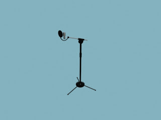
Also in this section of the room I created a mic stand. This wa made using mostly the cyclinder tool. The only new technique used in this object was to use the loft tool to make the tube that connected the mic shield to the stand.
The music stand was created by again using the cyclinder tool. The holes in the stand were created using the boolean tool.
Finally the sound proofing material was made by simply creating a spline in a zig zag shape and then extruding this up.


The Mixing Desk
To create the mixing desk I started off with the following image, this would be what my mixing desk would be based on:

To begin with I created a box and then cut out the side grates using the boolean tool. I then placed a chamfer box over the top of this base box. I increased the segments on the chamfer box, which would allow me to create the rubber grips on the side of the mixing desk. I converted the chamfer box into an editable poly and then selected the left and right hand polygons of the chamfer box. I then extruded these polygons so that the rubber grip looked to be slightly extruded from the main desk. I then detached these grips from the chamfer box so that it would be easy to apply the material to it.

Now it was just a case of adding the buttons to the object. The central buttons that would twist (for volume controls etc.) were made by firstly drawing a spline of a circle with grooves in it. This was then converted into a editable poly and extruded up. The top of this shape was then scaled down to give the correct look. A chamfered cyclinder was then added to the top of this button.
The sliders were made by simply creating a box making sure that there were a number of width segments. The polygons for the center of the box were then selected and the bevel tool was used to create a indent.
The final set of plug sockets were created by using the cyclinder tool and the tube tool.
Each of these set of buttons were copied and spread out over the main chamfer box. Finally the mixing desk screen was made using the box tool to create the thin shape for the screen.

The Easy Objects
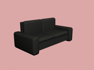
There were a few objects in my scene that were straigt forward to model, including the ceiling light, poster frames, standing shelf, sofa, the table and the standing lamp.


The ceiling light was created by a using the cone tool and also the cylinder tool. When making the three light shades I used the array tool to evenly spread the three connecters evenly. The lamp shades were made again using the cone tool. Chrome and glass materials were then added to this object from the arch materials library. The standing lamp was made from using the same tools.


The standing shelf was created by using the box tool. The shelves were then cut out of this box using the boolean tool.

The sofa and table were created using the box tool and also te chamfer box tool.


Tuesday, 9 December 2008
.....The Monitor
The inspiration of this monitor was my Dell Monitor that I use with my home computer
To the create the monitor I began with a rectangular shape and filleted the edges. This was then extruded up by converting the shape in to an editable poly. This was the beginning point of the monitor and would be the base. On top of this base shape I created a a box and this would be where the monitor stand would be connected to. Again this was converted in to an editable poly, I then selected the back edge and chamfered this a few times to created a rounded edge.

To create the main part of the stand, I again made a small box and converted this in to a editable poly. I then extruded the top face and moved it at an angle to create the first part of the stand. The other parts of the stand were created by again extruding faces and moving them into place.
To create the monitor a face from the stand was extruded slightly and then the outside face was scaled up to the size of the screen. A frame for the screen wa then made and the edges where chamfered to create the main part of the screen.
Now all that needed to be done was to create the label for the monitor along with the buttons. I did the buttons by simply creating a cyclinder shape and then converting to an editable poly. Then chamfered the edges to give the top of the buttons a more rounded feel.
The logo was created using the line tool. I just created the shape of the logo and then extruded this out.

Subscribe to:
Comments (Atom)